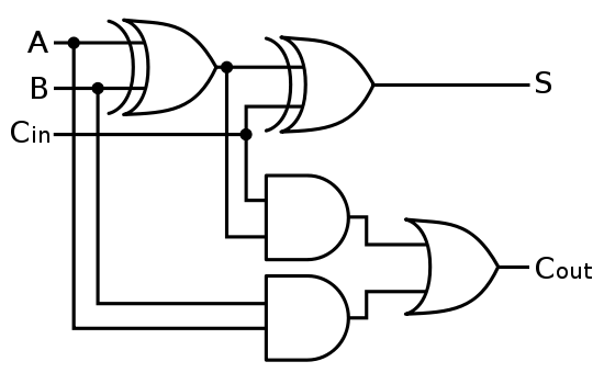
4 Bit Full Adder Circuit Diagram
Digital logic Full-adder circuit, the schematic diagram and how it works – deeptronic Full adder logic diagram
😊 Four bit parallel adder. 4 bit Binary adder circuit / block diagram
Let's learn computing: 4 bit adder/subtractor circuit Adder logic half boolean implementation Full adder logic diagram
Adder logic bit four diagram boolean half two simple adders answer so now
Adder theorycircuitAdder truth logic half sumador gates binario inputs datasheet combination suma microcontrollerslab Adder circuit diagram schematic bit works figureAdder logic circuitglobe robhosking compressor sum xor.
16 bit full adder digital circuit simulation using logisim softwareThe answer is 42!!: four bit full adder tutorial Full adder circuit: theory, truth table & constructionAdder subtractor bit make carry ripple verilog circuit binary diagram using 4bit want geeksforgeeks output hdl has source.

Full adder circuit diagram
Adder circuit construction binary circuits ibm sourav guptaAdder bit parallel four circuit binary diagram logic subtractor digital block example geeksforgeeks detailed discussion Adder circuit combinational ha sequentialExplain with example 4-bit bcd adder using ic- 7483..
😊 four bit parallel adder. 4 bit binary adder circuit / block diagramAdder logisim Adder bcd bit 7483 ic using explain example carry implementation13+ full adder block diagram.

Adder bit using circuit adders half four circuits implementation watson single just box latech edu
Adder logic wiring t1Combinational and sequential design of a 4-bit adder. (a) ha circuit Digital logicAdder subtractor bit circuit ripple carry diagram logic using project build only digital computing learn let its single indie electronics.
10+ adder circuit diagramCd4008 4-bit full adder ic pinout, working, example and datasheet Adder logic wiring calculatorsAdder subtractor bit circuit add sub questions overflow complement logic detection carry addition designing control zero line digital find.

Using bit half adders four circuit logic digital schematic circuitlab created electronics
.
.


Full-Adder Circuit, The Schematic Diagram and How It Works – Deeptronic

Adder - Classifications, Construction, How it Works and Applications

Let's Learn Computing: 4 bit Adder/Subtractor Circuit

Full Adder Logic Diagram - General Wiring Diagram

The Answer is 42!!: Four Bit Full Adder Tutorial

16 bit Full Adder Digital Circuit Simulation using Logisim software

Watson

😊 Four bit parallel adder. 4 bit Binary adder circuit / block diagram